Fantasy What-If Aircraft
From time to time I dream up fantasy aircraft from history, of varying degrees of impracticality or unlikeliness, and post them on the What-If Modellers forum. These are some that I spent a little time on; I have also edited and updated the text a fair bit here and there, and hope to do more of that. Be warned, the stitching together of arcane fact and outright fantasy is complex, subtle and the border line is often far from obvious.
Contents
- Dunne-Coanda delta
- Horten-Komet Mistel
- Northrop XP-56 derivatives
- Fairey Delta seaplane
- Triple-fuselage airliner
- Permanent soaring city
Dunne-Coanda delta
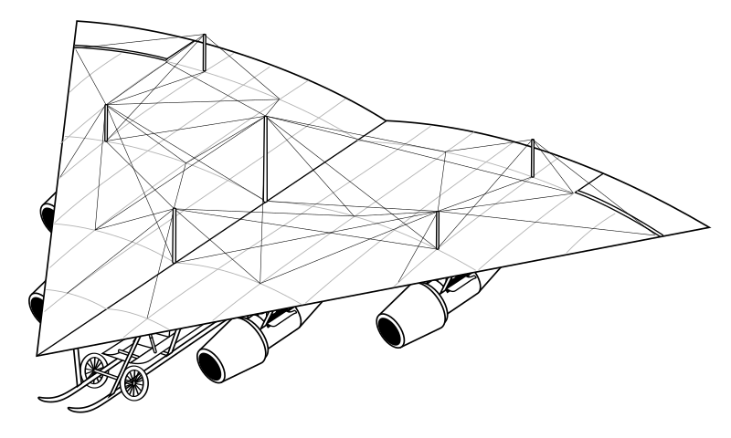
British aviation pioneer JW Dunne discovered the stable biconical delta wing, nowadays known as the Rogallo wing, in 1904. He patented it in 1909 (along with his more well-known tailles swept planform, which he had developed his delta into by 1905). Hungarian inventor Coanda built his grossly underpowered "jet" sesquiplane in 1910. The engine was not really a jet, but at best a hybrid ducted fan; the centrifugal fan was driven by a 50 hp Clerget piston engine and the "jet" bit was the intended entrainment of additional air mass with the efflux, to increase the thrust and efficiency. Unfortunately, it didn't.
I have discovered that they later collaborated on a new aeroplane. Coanda greatly improved his engine installation to match his laboratory predictions. Four of his new installations, based on the Green 50 hp water-cooled 4-cylinder inline engine (with which Dunne was already familiar), delivered sufficient thrust for the Dunne delta to take off, which it did at the Larkhill flying ground on Salisbury Plain in the spring of 1913. It was not particularly fast and was unable to carry any significant payload. Nevertheless it had good rough-field handling, as did all Dunne's designs, and was subsequently sold in small numbers to the War Office as a secret reconnaissance aircraft and, thanks to its size, sightings of it could be convincingly passed off as airships. Attempts to increase the engine thrust and airspeed tended to set the supporting struts on fire, so it was withdrawn from service in 1915. Note the curious double-hinge to the elevons, allowing them to curve but still function - Dunne patented that one too, ca. 1910 or 1911, and also built them into his more well known swept-wing monoplanes.
Construction was typical for monoplanes of the era, the wing being a fabric-covered woden frame and wire-braced, again after Dunne's habit, via a generous scatter of kingposts.
There was no real fuselage as such. The pilot sat in a kind of shallow tray under the nose, with the floor curved up at the front to (in theory) add a bit more lift - one of Dunne's less insightful patents.
Robust, rough-field undercarriage was a habit of Dunne's inherited from the early days when Farnborough Common and Shellbeach were infested with tussocks, rabbit-holes and drainage ditches. On several occasions its saved the pilot's life, including his, when attempting a cross-wind landing: there was no rudder, so no yaw control - you had to turn into the wind to land the thing. Turns were however neatly coordinated by the presence of proverse yaw when banking.
Dick Fairey, later to found his own far more successful company, was working for Dunne at the time. His pioneering abilities in the stressing of airframes were probably responsible for keeping the plane light enough to fly. The original drawings in the Science Museum archive bear his characteristic signature. This was the first Fairey Delta!
Horten-Komet Mistel
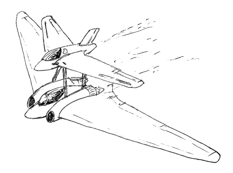
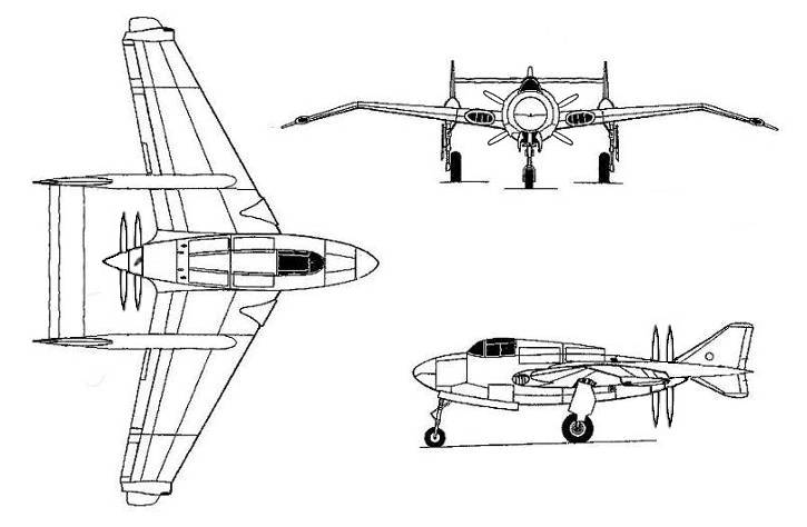
Mistel (Mistletoe) was a German WWII programme to pack unmanned, medium-sized aircraft with explosives, turning them into wing-borne cruise missiles. A piloted jockey fighter was mounted on top. The pilot would navigate to within range of the target, then aim and release the missile plane, before attacking any other targets of opportunity and, with luck, making it back over friendly territory before landing or baling out.
The Mistel programme was initially conceived and operated as a way to make effective use of obsolescent aircraft. Later on, its success led to studies employing more modern and faster types, including jets such as the Me 262.
Here, I push that to a high-speed, tailless conclusion. I offer the Horten Ho IX (Gotha Go 229) beneath an Me 163 Komet. The Me 263 would be a better choice, as that had longer range, could land more safely afterwards, and was contemporary with the Ho/Go flying wing. Still, they might well have used the more readily-available Me 163 for the initial development flights.
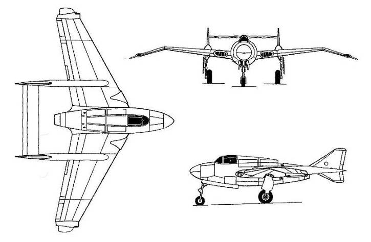
Northrop XP-56 derivatives
The real Northrop XP-56
Some readers will be familiar with the Northrop XP-56 "Black Bullet" project during WWII. It was a stubby little tailless fighter, of all-magnesium construction, with pusher propeller and gently-swept wings featuring curious turned-down wingtips.
Two examples were built. The first flew just long enough to establish that it was unstable and barely controllable, before it was destroyed when its nosewheel collapsed during high-speed taxiing trials. The second was heavily modified. It suffered nose-heaviness when the gear was down, while engine cooling was insufficient to sustain high power levels for high-speed flight. Today the machine is a museum piece.
So much is well known. Fewer people know that this was not the end of the project.
XP-56T
XP-56T
Northrop's magnesium-bodied pusher still had excellent high-speed potential. It was only the tailless aerodynamics and engine cooling that were wrong. A more conventional approach to the problem of jet exhaust was the twin-tailboom arrangement being worked on by de Havilland in the UK for its DH.100 Spider Crab, later renammed the Vampire. This twin-tail arrangement offered Northrop the opportunity to test various palliatives to the stability issues without endangering plane or pilot.
A third prototype was therefore built in this configuration, as the XP-56T. It proved a pleasant and predictable machine in the air, marred only by the endemic engine cooling issues.
Various techniques to improve the stability of the wing were tried, including leading-edge slats, tip endplate fins, deeper elevons and extensions to the downturned wing tips. The solution chosen was tip extensions which were rigged with a negative incidence to produce a downforce in level flight. Perhaps paradoxically to the uninitiated, this cured the stability issues. They also reduced the nose-heaviness experienced by the second prototype with the gear down. That's easier to understand: because they exert negative lift, one of the things they do is to push the tail down a bit, helping to lift the nose. Once up to speed, both flaps and undercarriage are raised together. The basic theory was worked out by J W Dunne between about 1904 and 1909. It was in fact Northrop trying to cut corners with Dunne's theory that had caused the aerodynamic problems in the first place.
XP-56JT and T
XP-56JT 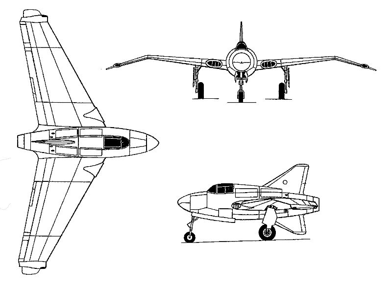
XP-56J |
The other big feature of de Havilland's design was of course its jet engine. By now, example engines were beginning to be shipped to the US. It was an obvious leap forward. Although the Vampire was a lighter craft than the XP-56 and with a smaller span, fuselage lengths were almost identical. Northrop therefore ripped out the troublesome piston engine installation and replaced it with a de Havilland Goblin jet. The Goblin fitted the XP-56 comfortably, using the same root-mounted air intakes that the piston engine's radiators had. The plan was to fit the more powerful Ghost engine when it became available (Which in the Vampire turned it into the Venom).
Northorp were now in a postion to build a tailless jet, the XP-56J. Based on the design of the second prototype with its enlarged central fins, the loss of stabilising rear area from the contraprop was compensated for by the enlarged the wingtip extensions. it was not finished until late in 1946.
It proved fast, manoeuvrable and – you can guess – politically the wrong machine in the wrong place and at the wrong time. It got tarred with the XP-79 flying wing brush when that programme stmbled, and was cancelled with the same red pen.
The XP-56J may have been fast by the standards of the day but it wasn't that fast compared to say the near-contemporary and similarly engined tailless swept de Havilland DH.108 Swallow. Being bigger it was really waiting for the more powerful engine, and while the tip extensions and oversized tail fins cured the instability they added drag. Max speed was 612 mph, comfortably faster than say the 580 mph of the Lockheed F-80 but less than the Swallow's 677 mph. With the planned engine and redesigned wingtips, max speed of the production version was estimated at 635 mph. That was uncomfortably close to the critical Mach number of the gently-swept wing, limiting the potential value of developing a more powerful engine.
The problem of directional stability was the one which the XP-56J wingtips addressed. If you have followed the above you will realise that they also increased longitudinal stability, one reason they had to be kept small.
Oh, and yes the Goblin was under-weight. It was accompanied by lead weights to obtain the correct balance. The more powerful Ghost planned for production was a heavier engine and would have located farther aft with a stretched tailcone, giving a properly balanced design.
The "J" was informally adopted. Officially, this was just the fourth prototype XP-56. The modifications were little more extensive than the changes made between the first two prototypes.
The production Ghost would of course have been license-built in the US.
Fairey Deltas
Fairey Delta seaplane
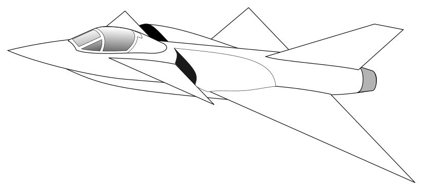
Initial design with symmetrical aerofoil
How do you keep the sea spray out of the jet engine intakes? Shield them with a canard foreplane! Here's Fairey Aviation going back to its roots as a supplier of Naval aircraft, not long after its Delta 2 broke the world airspeed record at over 1,000 mph:
Fairey chose a delta foreplane. As the angle of attack increases, its airflow quickly becomes dominated by the classic delta-wing vortex pattern. Airflow approaching the inlets is actually held downwards by the inboard walls of the vortices and smooth flow in the central region of the foreplane is maintained. Only the outer sections get the full vortex treatment. Note how the inlets are positioned inboard of the vortex zone to maximise the benefit of this effect. The foreplane is in effect unstallable and smooth airflow to the engines is assured at all angles of attack. Check out the intake location on the Convair F2Y Sea Dart if you want to know where best to put it on a tailless delta.
The practical issue is that the foreplane needs to be high-mounted so that pushes the inlets even higher. An annoying thing for the average landplane but it plays neatly into the hands of the seaplane designer. Look at the competition in the Secret Projects discussion (you have to join to see the piccies), most have inlets in silly places where either spray will flood the engines or the timidly-swept wing will starve them at high AoA when they are needed most. But by the time anybody started putting canards in front of delta wings, Convair's Sea Dart was just a memory and the era of the jet flying boat long gone.
Except, of course, for an obscure Admiralty requirement addressed by Fairey. The idea was to deploy a flotilla of high-performance warplanes in defence of islands and other Commonwealth territories which had had their runways trashed. By dispersing them and their support bases around suitable harbours, the high vulnerability, high cost and leisurely deployability of a large capital aircraft carrier could be overcome.
The support bases were a key part part of the weapon system and were containerised for fast air-freight delivery. They could even be pushed out the back of a Hercy bird, air-dropped into the waters of the harbour so no runway would be needed.
Fairey Delta seaplane II
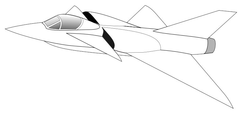
Second prototype with area-ruling and conical leading edge
A later refinement included the conical leading edges which had been introduced on the Convair F-102 production version, F-106 and B-58, along with better area-ruling, modernised canopy. a 1ft fuselage stretch to increase fuel capacity also necessitating a redesigned and slightly taller fin, and an uprated Avon with larger-diameter afterburner nozzle.
The conical leading edge sits inside the Mach cone of the leading edge root and, rather surprisingly, actually improves lift/drag ratio in supersonic cruise leading to greater range. It also improves low-speed handling. In the UK this last aspect happens to infringe on a 1909 patent by J.W. Dunne (as do all Rogallo deltas too). I'd love to find out when that patent lapsed as, although Dunne's company was formally wound up in 1919, the patent was in his own name and he did occasionally dabble in aeronautics after that.
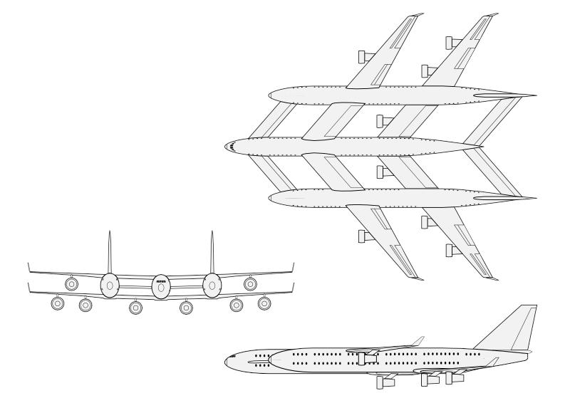
Triple-fuselage airliner
What is a practical shape for a giant aeroplane? Some of the design constraints, e.g. on the Airbus A380, are:
- Exit doors positioned to allow quick evacuation in an emergency.
- Wing root chord limited by need to evacuate.
- Wing span limited by airport handling facilities.
- Seat positions close enough to the aisles to allow quick evacuation.
- Engines and fuel positioned away from the passengers, for survivability.
- Giant structures are more difficult to keep both stiff and light enough.
- Huge inertia and scale require extra-powerful controls to respond quickly enough.
It is sometimes said that the flying wing airliner only makes sense on a huge scale. Some concept designs show a delta-shaped inner wing blending into slender swept outer sections. Engines typically mounted above the trailing edge. This is actually a rubbish idea that would never be approved because:
- Emergency exits are a problem. They cannot be directly downwards as the u/c might have collapsed on landing, if it was ever lowered. They cannot be directly upwards due to the need for injured passengers to climb up and also the time for that and to slide off the wing. In the leading edge they would need to be exceptionally precisely engineered, making them expensive, heavy and easily damaged. In the trailing edge they would need hugely lengthened doors that nevertheless could be easily opened by hand.
- Engines above and behind would crash down on the passengers if they broke free. They therefore require high-strength mountings and associated fuselage roof structure, which adds weight.
- Fuel safely stored in the outer wings would be a long way from the engines.
Some improvements could be made by moving the engines forward and down to the traditional hanging leading-edge pods. This would allow upper trailing-edge exit doors to operate by dropping down onto the floor to open. But passengers at the front of the delta would still be too far away, so that has to be abandoned and a more traditional swept wing of greater span used. A smooth cranking of the wing to give outboard dihedral would shorten the otherwise extra-long undercarriage while raising the tips clear of the ground at takeoff. This is opposite of the A380's gulled wing - one might even have an S-dihedral, with the intermediate section of each wing having reduced dihedral. But the big problem remains, how to accommodate such a huge wing span?
Another approach would be to take the A380 a few steps further. Its toothpaste-tube layout may not be the most elegant or ultimately efficient, but it is hugely practical. Nevertheless, scaling it up has its limits. The A380 is designed to accommodate a modestly stretched fuselage length, though airport terminals may not be. But the fuselage width is already limited by the need to avoid a deep auditorium-style room space, it is already taller than it can be made wide. A third deck would be a heavy, inefficient answer on such a fixed width. Better to add another fuselage or two. With the wing root chord and span already at the limits, one option is to fit a folding tip extension that hinges out of the way at the terminal, as Boeing are doing on the 777X. But that can only be taken so far, and it does nothing for the handling issues in the air. Some increase in the mid-section chord would help, also a lifting tail using relaxed static stability, a new foreplane so that the wing can be used more efficiently and possibly even a second wing in tandem. It all adds up, though it is also beginning to look very like a Burt Rutan design on steroids.
Here is my 3,000-seat megaliner, fully certified for accident safety and evacuation. Triple-bodied, tandem-winged four-surface configuration. 3,000 passengers, Six engines of GE9X/RR Ultrafan class. Fits within the 80m x 80m handling box of current major airports.
Permanent soaring city
A giant flying wing, this craft has no engines, but soars in the updraft found along Southern mountain ranges such as found in South America and New Zealand. It has an almost indefinite span, being on this scale flexible rather like some of the experimental ultra-lightweight solar aircraft. One can fly a new wing section up to it, bolt it on and then remove the ferry power unit.
Some engineering details:
The wing has a static centre of lift, meaning that it is stable in pitch and does not need a tail or a computer to keep it level. This is achieved using reflex camber on the rear section, so that the mid-line of the chord is a gentle s-curve, rather like this tilde character here: ~
Rather than having the whole structure flex, which would create unnerving creaks, groans and wobbly floors in turbulent winds, it is made in rigid sections with articulated joints like a railway train.
Some sections are bigger than the rest, creating relatively large - but very expensive - internal spaces.
There are some electric engines and propellers, and also wind turbines. Most are retractable, typically used in combination to maintain shape in varying local conditions. For example if a helicopter drops in on one section, it will deploy a propeller to help it maintain speed and height, while the neighbouring sections will deploy wind turbines which both supply power to the propeller and slightly drag these sections back to help smooth out the mechanical stresses. You may not realise it but such pop-out turbines are, on a much smaller scale, fitted as an emergency power supply on many aircraft flying today.
Other turbines would be permanent, supplying power to the aircraft's systems and inhabitants. But only limited power can be extracted, as the turbines act as airbrakes and the plane would drift backwards. Most likely, the inhabitants' lifestyle would require microwave beams from the ground, etc. to meet their full needs.
Larger deliveries of supplies would be by airship, as flying speeds will just be the natural windspeed in order to remain more or less stationary over the ground. Discharge of waste would be very strictly regulated - no blue ice here on a cold winter morning! Most would in fact go back down in the delivery airship as ballast.
After some years, a new ecology begins to establish itself on the ground beneath the aircraft's shadow. First it's the microorganisms, then the creepy-crawlies, but surprisingly quickly the characteristics of small birds, mammals, lizards and amphibians all begin to adapt to the rebalanced food chain. As those who were born in the sky city begin to grow old, identifiable new species begin to emerge in the twilight beneath.
Updated 9 Apr 2022