Vertex Figures
by
Guy Inchbald
Abstract
Mathematicians have used different definitions of the vertex figure for different purposes. They may be classified as intrinsic, dependent or polar types. The face of the dual polyhedron is reciprocal to the polar type of vertex figure. Nonconvex and asymmetric situations are considered. The complete vertex leads to a more general definition. All types are underpinned by a common abstract structure.
Recent change history
23 July 2020. More about the abstract and morphic, associated changes in terminology.
Introduction
Anyone who studies polyhedra with any seriousness will soon come across vertex figures. However it is not always clear what the properties of these figures are. When I needed to use vertex figures in earnest, I assumed that any vertex would have a unique vertex figure of definite geometrical shape, size and location. But this turned out to be naïve; different aspects of the problem used different definitions in the literature, and many polyhedronists seemed especially good at avoiding the issue of scale. One standard reference might describe them as like a cut across the corner of a polyhedron, another as a polygon drawn on a unit sphere, others explain that they are reciprocal to the faces of the dual polyhedron. How are all these properties connected? The truth is that in general they are not - "Vertex figure" is historically almost as loose a term as "polyhedron." Different definitions of a polyhedron lead naturally to different ideas about their vertex figures. Different investigators have tended to invent or borrow whatever kind of vertex figure they could understand or which helped them in their current work, sometimes with little regard for formal correctness. Confusion also arises from the way that for highly symmetrical forms, several different kinds of vertex figure may coincide, so that a single figure may have properties deriving from several unrelated principles. This has led many authors into ignoring or even confusing the different geometrical origins of these properties.
This essay is an attempt to bring some order and to clarity to the subject, including classification of the various types encountered. You will find the later parts easier reading if you have some understanding of geometric reciprocation and terms such as pole and polar (See for example Wenninger [12]), but you should find something of value here anyway. I should acknowledge the help of many colleagues in pointing out to me much of the information I now present here; only a few find mention in the text.
I have come to distinguish three general families of vertex figures, which I will call intrinsic, dependent and polar.
Intrinsic vertex figures
We will begin with a type of vertex figure which has perhaps the fewest technical problems, and which Prof. Johnson (after whom the Johnson solids are named) calls the vertex section. Assuming that all edges are at least one unit in length, if we construct a unit sphere centred on some vertex P (the vertex sphere), its intersection with the connected faces and edges is a spherical polygon, the vertex section. The vertex section for a cube is shown in Figure 1.
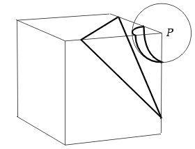
Figure 1 : Intrinsic vertex figures
Vertex sections have no significant mathematical problems, and can be applied to any vertex. The only niggle might be for very short edges where the assumption of a minimum length is false, but we can easily get round this by extending the lines of the edges along with the attached faces until they intersect the sphere, without causing any upset. Or we can just make the vertex sphere arbitrarily small, as Cromwell does [4].
Figure 1 also shows a flat vertex figure, cut across the cube. Flat vertex figures have some advantages, not least that they are easier to draw on a sheet of paper, and stand some chance of behaving properly when reciprocated with respect to a circle or sphere. In order to construct a flat figure, we must flatten out the vertex section in some way, either by taking a flat slice, rather than a sphere, a certain distance from the vertex at some defined point, or by projecting the spherical vertex section onto a plane. A common approach is to take points a unit distance from P along each edge, and then join them across the faces to form a polygon, again as if the corner had been sliced off (see for example Uniform Polyhedra [2]); this may be termed the unit edge type.
Other methods are to take a flat slice orthogonal either to the line joining the vertex to the centre of the vertex figure, or to the radial of the vertex (the line drawn from the centroid of the polyhedron, through the vertex). The plane intersects the chosen line at a point a unit distance from the vertex. These vertex figures are respectively of centric and radial type. The distinction may at first sight seem trivial; for most commonly-studied polyhedra these two lines, and hence these two vertex figures, align. But commonly-studied forms are usually highly regular - for less regular forms the distinction is important, as we shall see.
The radial type of vertex figure is, strictly speaking, a dependent type (which we will meet later), since its form depends on a distant feature which is the centroid of the polyhedron. All the others described so far are determined only by the local, or intrinsic, geometry of the vertex and are unaffected by the rest of the polyhedron. For example wherever three rectangles meet, the local geometry of the vertex, and hence also its intrinsic vertex figures, will be the same as for a cube.
Many vertex figures will appear similar, for example those of the regular tetrahedron and cube are both equilateral triangles. How do we tell them apart? We find that the various vertex sections stretch different distances round the vertex sphere and the included angles at the corners vary; in our examples that of the cube stretches further and has the larger included angle. If we project these onto a plane such that the sides are straight, they will have differing lengths of side. Knowing the projection used, we can find these as absolute (or ratio) lengths - but of course we would have to agree on the projection to use! So intrinsic vertex figures have an absolute size (or, for those made arbitrarily small, an absolute ratio of size to some standard feature such as the radius of the vertex sphere).
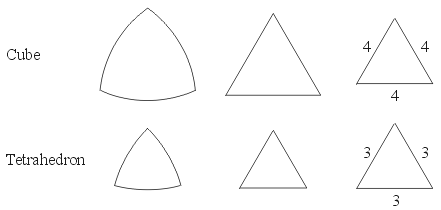
Figure 2 : Some flat intrinsic vertex figures
Figure 2 shows three types of intrinsic vertex figure for the cube and tetrahedron. The first is a stereographic projection of the vertex section. It preserves the corner angles of the vertex section, which are also the dihedral angles at which the faces meet. The second is the unit edge type and preserves scale: that for the cube is root two times that for the tetrahedron. For comparative purposes, with both these types it can be difficult to tell similar-looking figures apart, so the third type is less concerned with reproducing accurate dimensions, and instead annotates each side with the associated face type - 3 for a triangle, 4 for a square, etc.
Wenninger [12] applies Dorman Luke's construction (see later) to vertex figures of the unit edge type. He notes that this use of the unit length is a special case of taking any convenient length and so is essentially arbitrary. Such more general vertex figures and dual faces have fixed geometric shape but indeterminate scale. These may be called edge intrinsic, and include the unit edge type.
These methods all work fine for ordinary vertices, typically where there is a high degree of overall symmetry. But in less symmetrical situations flat vertex figures can have problems, which we will examine briefly.
For the edge intrinsic types the tangent points will not generally lie in a plane, resulting in a skew polygon. To obtain a flat figure, it may or may not be possible to substitute a centric figure.
For the centric type and for projected figures, in asymmetric situations there can be the problem of deciding the orientation of the cut or projective plane. An example is given later for a stellated icosahedron. The plane should be normal to the line joining the centre of the vertex figure to the vertex. But how does one define the centre of an asymmetric figure? From recent correspondence with Lem Chastain, Robert Webb and others, some polyhedra appear to defy any such attempt, so perhaps one should not take polygons for granted either. Don Hatch has written an interactive program which demonstrates the difficulty of defining such a centre, but has not been able to prove that no universal definition can exist.
For nonconvex situations such as certain stellations or the saddle-shaped vertices on the inside of a toroid, where parts of the vertex section extend to the "upper" half of the sphere, it is no longer possible to project the figure simply. If we try to maintain the general form, straight sides must become curved, or zoom off to infinity. It is the same problem as trying to make all great circles straight on a chart of the world's oceans. Alternatively, we can extend the upper faces and edges of the polyhedron down from the other side of the vertex, until they intersect the plane of the vertex figure, as explained later.
Dependent vertex figures
Some types of vertex figures vary according to the geometry of the polyhedron in which they occur. That is, their characteristics depend on the geometry of distant features of the polyhedron. The radial type has already been mentioned. Figure 3 shows two more varieties, half-edge and whole-edge, which are probably the most commonly encountered types of all. These may all be classified generally as dependent types.
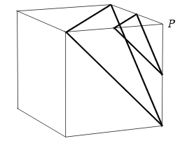
Figure 3 : Half-edge and whole-edge dependent vertex figures
To find the half-edge vertex figure, start by finding the mid-point of each edge connecting to vertex P. Connect these vertices up with new edges, lying in the faces of the polyhedron. These form a polygon, which is the vertex figure. For polyhedra having an intersphere (also called the midsphere) tangent to all edges, the intersection of the dual face plane (or polar - see later on) with the intersphere is both the circum-circle of the vertex figure and the in-circle of the face of the dual polyhedron, so these two polygons lie in a reciprocal relationship about the circle [3]. Dorman Luke's method for constructing the dual face from the half-edge vertex figure for uniform polyhedra is described by Cundy & Rollett [5] and illustrated (without acknowledgement) by Holden [7]; the variant mentioned earlier is well illustrated by Wenninger [12] and results in duals which are similar to Cundy & Rollett's but of different size.
The procedure to find the whole-edge vertex figure is almost the same. From P, follow each connecting edge all the way down to the vertex at the other end. Connect these vertices with new edges as before to obtain the vertex figure. Coxeter et al define this type in Uniform Polyhedra [2] before choosing instead to use the unit-edge intrinsic variant already described. Skilling [10] sticks to this type, which is perhaps more practicable for his computational approach.
Facetting (or faceting) is the process of removing parts of a polyhedron without adding any new vertices, to create a new polyhedron. As a result, new faces are exposed which are said to be facets of the original (though some authorities disagree with this terminology). Whole-edge vertex figures turn out to be such facets, though note that not all facets are vertex figures and no other types of vertex figure are facets.
For a highly symmetrical polyhedron, the dependent vertex figures are similar to the planar intrinsic ones. In the case of the cube for example, all these types are equilateral triangles. But consider an elongated cuboid; the intrinsic figures are unchanged from the cube, while the dependent figures become distorted as shown in Figure 4.
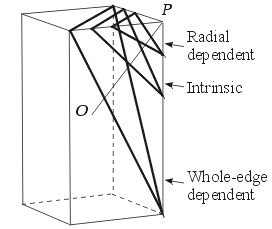
Figure 4 : Intrinsic and dependent vertex figures for an elongated cuboid
The edge dependent figures follow the elongation of the cuboid. The radial dependent figure remains orthogonal to the line OP (where O is the centre of the cuboid), and tilts the opposite way from the others.
The size of a dependent vertex figure will not help us to find the angles of the polygon corners at the vertex, as it did with the intrinsic ones. Nor will its shape tell us which corners are similar. Instead, we must refer to the polyhedron to which the figure is attached (i.e. on which it is dependent). Numerical annotation, as with intrinsic figures, is commonly used. Only in special circumstances, such as uniform polyhedra having a common length of side, can we use comparative shapes and sizes.
As with most intrinsic vertex figures, for complicated polyhedra the edge dependent types may not be planar. This may be acceptable if we are happy to accept such skew figures, otherwise they must be projected onto a plane as some other type of vertex figure.
Polar vertex figures
Before proceeding, the distinction between the terms "dual" and "reciprocal" should be explained. Duality is a general topological property which relates pairs of structures. A geometric polygon or polyhedron may be reciprocated about some circle or sphere (or indeed any conic or quadric) to obtain a reciprocal figure having the dual topology to the original, a "geometric dual". Where there is no risk of confusion in the text, the concise term "dual" may be used.
It is an oft-stated principle that the face of the dual polyhedron is the (2D) dual of the vertex figure of the original. The beautiful software application Great Stella [11] makes good use of it; to quote the author (in private correspondence), "There is such a strong connection between vertex figures and dual faces, that ... the two should be derived from the same reciprocation sphere." We previously noted certain polyhedra for which the half-edge vertex figure has this property. However in general the particular reciprocating circle we used earlier may not exist, for example where a polyhedron has no intersphere. In leaving the more regular arrangements behind, we find that we also depart from the standard treatments of vertex figures.
To begin with, the dual face plane (the polar plane, or polar) may lie a long way from the vertex (the pole). To obtain a 2D reciprocal relationship, the vertex figure must be projected onto the polar plane, as a polar vertex figure. We will also need a general way to find the reciprocating circle. To determine the precise geometry, we need to know the geometry of the reciprocating sphere. Traditionally the sphere is concentric with the polyhedron, and we will use this for now. But in general this need not be the case and in some cases the polyhedron may have no definable centre. We will look at such asymmetry later.
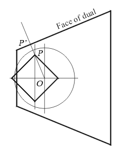
There are two general situations, depending on the locations of the vertex and dual face. Figure 5 shows the more commonly studied one, in which the vertex P (pole) is outside the sphere and the plane of the dual face (polar) intersects the sphere. The inverse point P' is the centre of the circle of intersection. The polar axis, on which O, P' and P lie, is normal to the polar. The circle of intersection is shown here in false perspective, as if seen from a shallow angle. It conveniently turns out to be the circle of reciprocation. This is the situation whenever we use the intersphere.
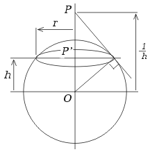
Figure 5 : Sphere and circle of reciprocation
For a sphere of radius 1 and distance OP' from centre to polar of h, the radius r of the reciprocating circle is given by:
r2 = 1 - h2
Consider the elongated cuboid again. Let us add a concentric reciprocating sphere of suitable radius (Figure 6). The dual polyhedron is a flattened octahedron: the face dual to P lies in its polar plane and is irregular. The 2D reciprocal to this face (shown bold in Figure 6) follows suit and is a polar vertex figure of the cuboid. Comparing Figures 4 and 6, we see that in this particular arrangement, where the polyhedron and sphere are concentric, the radial dependent figure happens to have the same orientation and shape as the polar one, but may have differing location and scale. This is not generally the case.
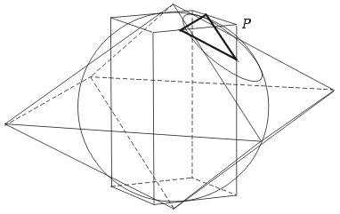
Figure 6 : Dual octahedron and polar vertex figure (bold) for the elongated cuboid
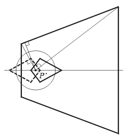
Less commonly studied is the situation where the vertex lies inside the reciprocating sphere and the polar plane wholly outside. The polar no longer intersects the sphere. If we now attempt to solve the above equation for h > 1, we find that r2 < 0. That is, r either does not exist or is imaginary. The position of the reciprocating circle is thus not immediately clear.
What now of the idea that "the vertex figure is the reciprocal of the face"? Do we have to say that the vertex figure is no longer reciprocal to the dual face, or can we find some more general definition for the reciprocating circle?
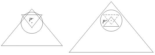
To help visualise what is going on, start with a large cuboid whose vertex lies outside the sphere, and think of it shrinking so that 1/h decreases steadily. The vertex figure, which lies in the polar, starts near the centre of the sphere and moves upwards as h increases. The vertex figure is tangent to the faces of the polyhedron, and the faces converge on the vertex, so as the vertex figure gets nearer the vertex, it shrinks. This is the situation shown in Figure 6, with the arrangement on the polar redrawn more clearly in Figure 7(a). At the point where the vertex reaches the sphere and h = 1, the vertex figure becomes infinitesimal.
 |
|
| (a) | (b) |
| Figure 7 : Arrangements on polars at different distances (not to scale) | |
As the cuboid continues to shrink, the polar moves on upwards beyond the sphere and h continues to increase. The vertex figure reappears and starts growing again, but is now inverted. Because of this it appears not to lie in a reciprocal relationship with the dual face any more. But appearances can be deceptive - notice that there is no longer a circle of intersection, so something odd must have happened to the circle of reciprocation.
The new arrangement is shown in Figure 7(b), to which I have added a dashed figure which is the inversion of the vertex figure in P'. We find that the dashed figure and the face of the octahedron are reciprocal figures about a circle centred on P', also drawn. The inverse relationship between the vertex figure and the dual of the face is straightforward enough, but this plane does not meet the sphere - so where does the circle come from?
If we follow the locus of the circle with increasing h, we obtain the hyperboloid shown in Figure 8. This surface is tangent to the sphere at its lowest point and is asymptotic to a 45 degree cone with apex at the sphere centre (only one side of the cone is shown).

Figure 8 : Imaginary circle of reciprocation
Let us align the polar axis with the z axis, with O at the origin (i.e. h = z). The sphere is now the solution of
x2 + y2 + z2 = 1
for real x. The hyperboloid is the solution of the same equation, for real z but imaginary x and y. Since
r2 = x2 + y2
we find that r2 must be negative and so r must also be imaginary. The circle has indeed become imaginary. The circle that I have drawn in the face plane is called the real conjugate of the imaginary circle.
In the equation we met earlier, h is now greater than 1, so we confirm that r2 has become negative. We can readily see that this is also true when h < -1, confirming that the hyperboloid has a second half (as all good hyperbolae should) on the opposite side of the sphere.
Figure 9 shows an enlarged detail of Figure 7(b), on which a pole Q and its inverse point Q' in the polar have been labelled. Because the vertex figure is inverted, Q and Q' lie in opposite directions from the centre. We will say that the distance P'Q has a positive sign, so P'Q' is negative. From P'Q x P'Q' = r2 we again find that r2 is negative. This shows how the imaginary nature of the circle is linked to the inversion of the vertex figure.
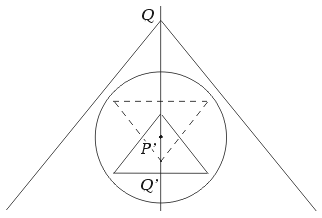
Figure 9 : Inverted vertex figure
As we shrink the cuboid further, P approaches the centre of reciprocation and 1/h becomes small. The polar moves out towards infinity, and the dual face, reciprocating circle and vertex figure all approach infinite size.
For certain types of polyhedron the reciprocal relationship between polar vertex figures and dual faces may not be of much value, or even make any sense. Grünbaum's polyhedra with skew faces have been mentioned before. I don't know if reciprocating such a skew face has any meaning - there is no plane for the figure to lie in, so in the case of a polyhedron there would thus be no unique reciprocal vertex. One could perhaps fill the figure with a curved surface, say the minimal surface, and then reciprocate that in a sphere - which should, I guess, result in another curved surface - but trying this seems to land us in all sorts of difficulties. Apeirohedra (polyhedral structures having an infinite number of faces, and so extending infinitely) have no identifiable centre so the location of the sphere must always be arbitrary, and congruent faces or vertex figures do not in general have congruent duals.
Nonconvex vertices
For nonconvex situations such as certain stellations or the saddle-shaped vertices on the inside of a toroid, where part or all of the vertex section extends to the "upper" half of the vertex sphere, it is no longer possible to project the figure simply. Sides must become curved, or the upper features "folded back" and overlaid on the lower features.
One approach might be simple parallel projection onto a plane. The perspective sketch in Figure 10 shows the region of a polyhedral surface around a 3-fold saddle vertex, on which an edge intrinsic vertex figure is drawn. This figure is projected vertically downwards onto a horizontal plane beneath. To the right, the projected figure is reproduced in the plane of the page.
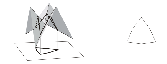
Figure 10 : Parallel projection of a saddle vertex figure
One disadvantage of this projection is that features lying approximately halfway up the vertex sphere will tend to lie in an unhelpful clutter around the rim of the projected figure. Note also that the figure is similar to that of some other ordinary convex vertex.
An alternative projection is obtained by extending the faces and edges of the polyhedron down from the other side of the vertex, until they intersect the plane of the vertex figure, as in Figure10.
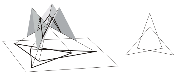
Figure 11 : Saddle vertex figure as intersections of planes
Notice that the extension moves some corners to the opposite side of the figure, which makes it similar to that of some other star vertex. This can be confusing, however this type of projection is worth understanding because it occurs naturally in the polar types, and is the preferred projection for the flat intrinsic and radial dependent types.
Other curious effects occur with concave vertices, which lie at the bottom of hollows. At first sight such a figure might appear as an ordinary convex one. However the figure is "inside-out", with the interior of the polyhedron appearing outside it. Because of this the figure has also changed sense; a clockwise sequence of corners A, B, C, ..., n has become the clockwise sequence n, ..., C, B, A.
For all these kinds of non-convex vertex, without prior knowledge of the geometry of the vertex, the figure is ambiguous. Authors reproducing such figures would be wise to annotate them accordingly.
An unambigous flat vertex figure may be obtained by stereographic projection of the vertex section, as in Figure 2. The disadvantage is that sides above the vertex become extremely distorted into large circular arcs.
Asymmetry
Figure 12 shows a side view of a regular octahedron, whose intrinsic vertex figure at P is a horizontal square. A reciprocating sphere is located slightly offset to one side, distorting the dual cube into a square frustrum (truncated pyramid). The axis of symmetry of the vertex is no longer a radial of the sphere. The polar is likewise no longer parallel to any intrinsic or dependent vertex figure. The frustrum's upper face lies in the polar, and is neither square nor horizontal. Extending the faces and edges of the octahedron until they intersect the polar yields a polar vertex figure in the shape of a kite (Figure 13).
 |
 |
| Figure 12 Asymmetric reciprocation | Figure 13 : A polar for an asymmetric arrangement |
In Figure 13 the inversion of the polar vertex figure about P' is shown dashed. Some construction lines have been drawn in, to help illustrate the inverted figure's reciprocal relationship with the dual face, and a real image of the reciprocating circle is drawn.
Now for an example even further from the ordinary but of a type often encountered with stellations, toroids and other nonconvex polyhedra. Figure 14 shows a certain dodecagon.
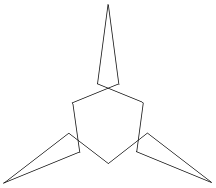
Figure 14 : Dodecagonal face of a stellated icosahedron
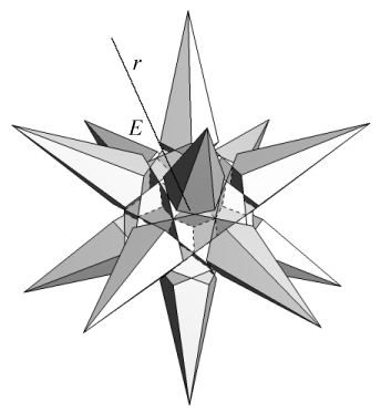
Twenty of these form a stellation of the regular icosahedron (Noted by Bridge [1] as D + f2), to which I have added the polar axis r to vertex E in the general and detail views of Figure 15.
 |
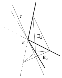 |
| Figure 15 : General and detail sketch views of a stellated icosahedron | |
Dual to the stellation is a certain facetting of the regular dodecahedron, and dual to the vertex (in 3D) is a face, or facet, of the type I have elsewhere labelled E [8]. This face and the (2D) dual vertex figure (triangle E2 in Figure 15) are normal to r and have a very different orientation from the plane of the intrinsic vertex figure (triangle E1). While E1 lies by definition inside the solid, E2 lies outside!
For certain types of intrinsic figure, such as the centric type, there is also the problem of orienting E1, as was discussed earlier.
Abstract vertex subtopes
All these different kinds of vertex figure share one thing in common. For any given vertex they all have the same combinatorial or topological structure of individual parts which are incident one with another. This incidence structure thus provides a unifying background to all the types and its theory similarly provides a unifying background model for all vertex figures. As an incidence structure a vertex figure may be understood as the set of all its parts, partially ordered by a ranking order and an incidence relation. A partially-ordered set of this kind is called an abstract polygon and is a two-dimensional example of the more general abstract polytope in any number of dimensions.[6][9] For more about abstract polytopes and the terminology I use here, see A Critique of Abstract Polytopes.
To create a recognizable geometric figure such as a polyhedron, its abstract structure or topology must be "realized" by mapping its parts onto geometric space. The choice of mapping is arbitrary. The abstract figure has no geometry, so geometric properties of symmetry or starriness, of regularity, convexity, winding and covering, emerge only as a consequence of the chosen mapping. For example all convex and star pentagons have the same abstract structure; it is only as realizations that they gain their geometric properties.
An abstract vertex figure is itself a subset, sub-polytope or subtope of the whole abstract polyhedron. In fact it is so abstract that it is not yet identified specifically as a vertex figure, it is merely a vertex subtope. When realized as a part of the parent polyhedron it appears as a vertex star. The vertex star is the set of parts of a polyhedron which are incident on the vertex. These include the faces and edges which meet at the vertex, together with the body of the polyhedron and the vertex itself.
When we polarise a face and its boundary in three dimensions, the result is the dual vertex star. But if we instead polarize the face-with-boundary in two dimensions the result is the dual vertex figure. The vertex figure retains the abstract structure of the vertex star, but it maps it to one dimensional level lower - for example an abstract side maps to a point in the vertex figure. The star and the figure are the same abstract polygon, the one realized in 3-space and the other in the plane.
The complete vertex
There is nothing to stop us realizing each part of a polyhedron as a whole subspace; a face as a plane, an edge as a line. The face planes and edge lines incident on a given vertex, together with the vertex point itself, comprise what we may call the complete vertex. It is comparable in some ways to the complete figures met in other branches of geometry, such as the complete quadrilateral. More generally there is no need for the subspaces to be flat; a curved surface with geodesic lines drawn on it would do just as well.
Just as any side of the vertex figure lies in a face plane or surface, so the interior of the vertex figure lies in the body space of the polyhedron. The complete vertex is just another realization of the abstract vertex subtope.
A vertex figure is now generally defined as any (realization of a) vertex subtope whose parts lie uniquely in each and every subspace of the complete vertex. As we have seen, such a figure may be planar, skew or arbitrarily curved (e.g. spherical).
Almost all the types of vertex figure we have discussed lie in the flat face planes and edge lines incident on the given vertex, and as such are examples of the general definition just given. Where we wish to discuss such figures without reference to a particular type, we may refer to the abstract vertex figure. The remainder (such as in Figure 10) are projections of such vertex figures onto a flat plane; we may justifiably regard such a projected figure as a mere representation of the true figure.
Morphic vertex figures
It can be useful to understand realization as a two-step process. The first is that of of interpretation, in which we decide how to interpret the abstract parts. The vertex star, vertex figure and complete vertex are all different interpretations of the parts of the vertex subtope.
In the case of a polyhedron we interpret the faces as surface regions, edges as linear segments and vertices as points. The incidences between these define a topological manifold, a kind of dimensionless "rubber-sheet" surface which I call a morphic polyhedron. For more about morphic theory, see my page on Morphic Polytopes.
The second step of realization is that of concretization, in which the manifold is immersed in some containing space, typically Euclidean space, and the various parts are given their geometric properties such as size and shape. Usually we will want them all to be flat.
However vertex figures must be interpreted slightly differently. The abstract body becomes a plane region, faces become line segments and edges become points. The result is a structured but shapeless morphic polygon. Such a morphic polygon is clearly no longer a vertex star or a complete vertex. It still underlies all the related vertex figures of whatever type, which may now be concretized as required.
Thus, morphic theory helps to clarify the relationship between the abstract and the geometric variations in what I hope is a useful way.
Conclusion
Figure 16 shows some vertex P at which three edges and three faces meet. The edge lines and face planes extend in both directions. There are many possibilities for the vertex figure, two of which are shown, but which is correct?
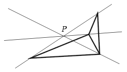
Figure 16 : Two possible vertex figures
For an intrinsic vertex figure we must ask which region of space around the vertex is interior to the polyhedron (or if this is not evident, as it need not be, which regions of the planes between edge lines are boundaries of the polyhedron). For a radial dependent figure we must ask where is the centre of the polyhedron. For an edge dependent figure we must ask not only which lines are edges of the polyhedron, but also how long they are. And for a polar vertex figure we must ask for some information about the reciprocating sphere and/or the dual polyhedron. We have found that the various answers can all lead to very different figures for the same vertex.
For a polyhedron having all connecting edges of length 2, the unit-edge intrinsic and half-edge dependent vertex figures coincide. Where the polyhedron has an intersphere (these include regular, uniform and canonical polyhedra among others), the centric and radial types coincide, as also may the edge intrinsic type of appropriate size. Where this sphere is then used as the reciprocating sphere, the polar vertex figure coincides with the unit-edge and half-edge types: in such circumstances it is easy to forget the derivation of the figure and to become confused over the relationships between its various properties. Unfortunately the more well-known studies have tended to confine themselves to just these circumstances, with confused results. The Dorman Luke construction is a typical example of this. It is traditionally introduced in the context of an edge intrinsic or edge dependent type of figure, however we now see that it employs a special case of the polar type.
Here is a list of all the types and sub-types of vertex figure identified:
- Topological: Abstract, morphic, complete.
- Intrinsic: Vertex section, edge (including unit edge), centric.
- Dependent: Radial, half-edge, whole-edge.
- Polar: Real and real conjugate.
- Projected: Not strictly vertex figures but representations of them. And still valid realizations of the abstract.
We have seen that there is no single "correct" definition of the vertex figure; they are all of equal topological validity and it is easy enough to transform any kind into any other. Indeed if one is interested in the vertex figure solely as a topological diagram of the "structure" of the vertex, one might as usefully work with the vertex star. For the rest of the time, their metric properties can differ wildly and you must choose the one that works for you.
For general analysis the vertex section has least problems, but for presentation on paper it must be projected onto a plane. When exploring shapes and making models, whether physical or mathematical, the edge dependent types simplify life. When studying duality the polar type is most advisable, and in the more regular situations its identity with other types is an intriguing line of study. The main thing is to be aware of the type you are working with, and not to confuse its properties with those of the other types.
The ideas of polygon (2D) and polyhedron (3D) may be generalised in n dimensions as an n-dimensional polytope or n-tope. A vertex figure of an n-tope is a polytope in (n-1)-dimensions, or (n-1)-tope. Although this essay has avoided discussing such figures, the various kinds of vertex figure identified are also directly applicable in other dimensionalities.
References
NOTE. References [6], [9], and [10] are highly technical, and are recommended only to the advanced reader.
[1] N.J. Bridge, Facetting the Dodecahedron, Acta Cryst. A30 (1974) pp. 548-552.
[2] H.S.M. Coxeter (et al), Uniform Polyhedra, Phil. Trans. 246 A (1954) pp. 401-450.
[3] H.S.M. Coxeter, Regular Polytopes, Dover, New York (1973).
[4] P. Cromwell, Polyhedra, CUP pbk. (1999).
[5] H.M. Cundy and A.P. Rollett, Mathematical Models, OUP (1961).
[6] B. Grünbaum, Polyhedra with Hollow Faces, Proc of NATO-ASI Conference on Polytopes ... etc. (Toronto 1993), ed T. Bisztriczky et al, Kluwer Academic (1994) pp. 43-70.
[7] A. Holden, Shapes, Space and Symmetry, Dover (1991).
[8] G. Inchbald, Towards Stellating the Icosahedron and Faceting the Dodecahedron, Symmetry: Culture and Science Vol. 11, 1-4 (2000) pp. 269-291.
[9] P. McMullen and E. Schulte, Regular Polytopes in Ordinary Space, Discrete Comput. Geom. 17 (1997) pp. 449-478.
[10] Skilling, The Complete Set of Uniform Polyhedra, Phil. Trans. 278 A (1975) pp. 111-135.
[11] R. Webb, Great Stella, software, http://www.software3d.com
[12] M. Wenninger, Dual Models, CUP hbk (1983) ppbk (2003).