Facetting Diagrams
Updated 18 July 2004
The text of this article is substantially reproduced by kind permission from:
Inchbald, G.; "Facetting Diagrams", The Mathematical Gazette 90, July 2006, p.p. 253-261.
A few minor corrections have been made.
Introduction
Facetting, or faceting, is the process of removing parts of a polyhedron, without creating any new vertices. It has received far less attention than the process of stellation, which is its exact reciprocal. Facetting is perhaps less easy to visualise clearly, and the results may not initially have the same appeal. But once broached, it has a fascination all its own. Also, to properly understand the rules of stellation, it can be illuminating to study the reciprocal rules of facetting. Now that suitable software is available (see Further investigations), the study of facetting is gaining momentum.
Any two vertices may be joined by a line. Typically, this line will be contained inside the polyhedron. If several such lines connect in a planar circuit, they form a complete polygon, or facet, inside the polyhedron. Again, several such facets may connect to form a complete polyhedron inside the original one. The original is the base polyhedron, and the new one is a facetting (sometimes spelled faceting) or called a facetion of it.
All the possible edges and facets which can meet at a given vertex of the polyhedron can be shown in the facetting diagram. This diagram makes the study of facettings easier, just as the stellation diagram helps in the study of stellations (The stellation and facetting diagrams are actually dual to each other, so each diagram can also give illuminating insights into the other).
The five Platonic regular solids provide convenient examples to introduce these facetting diagrams. A regular or uniform polyhedron has congruent vertices, so a single diagram will do for all its vertices. Each such polyhedron has its own characteristic diagram.
Tetrahedron
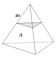
The simplest of all polyhedra is the tetrahedron. It has three faces and three edges meeting at a vertex, and is shown with one of its vertex figures (shaded) in Figure 1. The bold A indicates all faces within the symmetry group of the one labelled, and the bold m indicates all edges within the corresponding symmetry group.
 |
 |
|
| Figure 1 : Tetrahedron with vertex figure | Figure 2 : Vertex figure (and facetting diagram) of the tetrahedron |
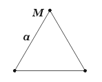
The vertex figure can be loosely thought of as the figure exposed when a corner of the whole polyhedron is sliced off, and shows the connecting faces and edges at the vertex. It is drawn accurately in Figure 2. The corners are shown here as little dots; this will help identify them in the more complicated diagrams we will be meeting later. Labels a and M identify sets of congruent features within the symmetry group of the polyhedron (and hence also of the vertex figure). Notice that sides a are sections of the three congruent faces A, and points M are sections of the three congruent edges m.
No other lines between vertices can be drawn, so the tetrahedron has no other facets. Consequently the facetting diagram shows just those of the base tetrahedron and, rather trivially, is identical to the vertex figure.
Cube
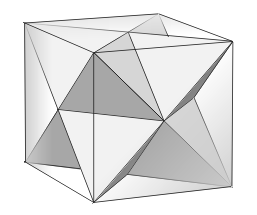
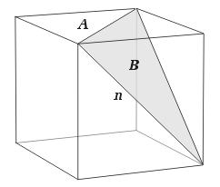
Any facetting shares the same vertices as the original polyhedron. The regular compound of two tetrahedra, or stella octangula, is a well-known facetting of the cube. They are shown together in Figure 3, and one of the stella octangula's triangular faces is shown in Figure 4.
 |
 |
|
| Figure 3 : Stella octangula as a facetting of the cube | Figure 4 : Triangular facet B of the cube |
The facetting diagram of the cube is shown in Figure 5. Sides a are sections of the square faces of the original cube and b are of the triangular faces of the stella octangula. Points M section the edges of the cube and N those of the stella octangula, which are also the diagonals of the original square faces.
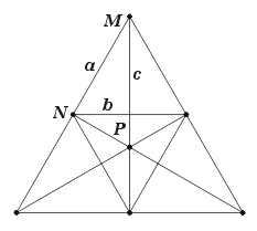
Figure 5 : Facetting diagram of the cube
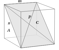
Now let's look at how to use the facetting diagram to find new edges, facets and facettings. The diagram for the cube includes an additional point in P, representing a candidate edge p connecting to the vertex at the far corner of the cube. A set of lines c connect each M point to the opposite N point and represent candidate facets C. P also lies in each of these planes, allowing us to deduce that each such facet has four vertices – the vertex which is the subject of the figure, plus one each at the end of the m, n and p edges. P is part way along c, so p must be a diagonal of the facet. Tracing all this out on the cube, we obtain the facet shown in Figure 6.
 |
 |
|
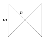
| Figure 6 : Rectangular facet C of the cube | Figure 7 : Sub-facet of the square A |
There are six such facets, but they do not meet along their edges to form a polyhedron. To achieve this we will need to add another type of facet. One type that will do the trick may be obtained from the original square faces by adding the diagonals and removing two opposing sides, as shown in Figure 7. We may call this a sub-facet of the original square.
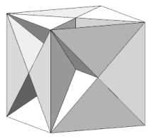
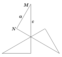
The resulting polyhedron is shown in Figure 8. The c faces pass through its centre, each dividing it in half, so it is a "hemi" polyhedron. It does not have the full symmetry of the cube, so may be classed as a subsymmetric facetting. Its vertex figures are handed, or chiral, having left- and right-hand forms alternating around the polyhedron. One is shown in Figure 9.
 |
 |
|
| Figure 8 : Hemi facetted cube | Figure 9 : Vertex figure of the hemi facetted cube |
If the various vertex figures of the cube, stella octangula and hemi facetted cube are all superimposed, the original facetting diagram is formed. Thus, the facetting diagram is a kind of "complete vertex figure" from which the vertex figures of individual facettings may be obtained. By tracing different circuits (i.e. polygons) in the diagram, the various facettings can be found. In the case of the cube there are several more subsymmetric ones.
Note that for subsymmetric facettings, it is not necessary for all vertex figures to be congruent; I have only done so here for convenience in treating the fully symmetric facettings. Notice also that although the facet in Figure 6 can be subdivided into further, cross-quadrilateral facets in the same manner as the square in Figure 7, these facets meet at c in threes, which is not usually allowed for polyhedra.
Octahedron
The octahedron has three diagonal planes passing through its centre. Two of these are seen as b in the facetting diagram shown as Figure 10 (the third is parallel to the plane of the diagram).
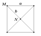
Figure 10 : facetting diagram of the octahedron
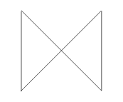
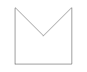
Several subsymmetric facettings may be obtained, of which two are described here. The tetrahemihexahedron has alternate faces of the octahedron removed to expose the square diagonal planes, giving it tetrahedral symmetry. Its vertex figure is shown in Figure 11. Another facetting has two opposing faces of the octahedron removed, giving it the symmetry of the triangular antiprism. Faces B are sub-facetted similarly to Figure 7 and the vertex figure is shown in Figure 12.
 |
 |
|
| Figure 11 : Vertex figure of the tetrahemihexahedron | Figure 12 : Vertex figure of the "antiprism" facetting |
Note how, again, the vertex figures are contained in the facetting diagram.
Icosahedron
The icosahedron has three sets of internal facet planes, shown as b, c and d in Figure 13.
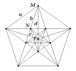
Figure 13 : facetting diagram of the icosahedron
Those identified as b are the pentagonal faces of the great dodecahedron. Each such face has diagonals N which bound a pentagram sub-facet – a face of the small stellated dodecahedron. Those identified as c are the triangular faces of the great icosahedron. The hemi facets identified as d are not part of any fully symmetric facetting. I have not explored the subsymmetric ones – you might like to.
Dodecahedron
The dodecahedron is altogether more complicated, as the facetting diagram in Figure 14 shows. For a start this polyhedron has many more connecting lines and planes, and many more opportunities to find sub-facets. Notice also that the p edges are chiral, having distinct d (dextro, or right-handed) and l (laevo, or left-handed) subsets.
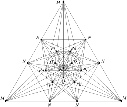
Figure 14 : facetting diagram of the dodecahedron
A little investigation reveals several regular triangles embedded within the diagram. These are vertex figures of well-known polyhedra. The segments QQ of lines NQQN form the vertex figure of the great stellated dodecahedron. The lines NPN form two overlapping triangles, which is the vertex figure of the regular compound of five cubes. The segments PdQPd of lines MPdQPdN form the vertex figure of the chiral regular compound of five tetrahedra. The l set likewise leads to its chiral twin, and together they form the vertex figure of the compound of ten tetrahedra.
Some of the facets are irregular figures having more than one type of corner. Such facets in a given set will therefore appear in the diagram as more than one type of line. That is, the lines will not all be congruent (though all lines in a congruent set will always belong to the same type of facet). But this is going well beyond a simple introduction, and so is a good place to stop. If you wish to dig deeper into the dodecahedron, some further reading is given below.
Further investigations
A facetting diagram can be determined for any vertex of any polyhedron. For example, those for the cuboctahedron and truncated tetrahedron are shown in Figures 15 and 16 respectively.
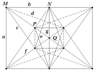 |
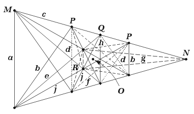 |
|
| Figure 15 : facetting diagram of the cuboctahedron | Figure 16 : facetting diagram of the truncated tetrahedron |
In each case, the facet sets are identified by the letter sequence a, b, ... , starting from the facet furthest from the polyhedron centre, and moving inwards. Notice that some facet sets appear as more than one type of line, representing different corners of the facet. I have drawn some of these sets as dashed lines, to help identify them and to reduce the clutter of identifying letters. The edge sets are likewise labelled as M, N, ... .
For the truncated tetrahedron, the points O lie on the lines connecting the vertices to the centre of the polyhedron. No lines pass through them, so there are no hemi facets.
Any set of facets, which exactly forms one or more polygons in the facetting diagram, will have no open edges and so will also form a polyhedron which is a facetting of the base polyhedron. This is one of the most useful features of the diagram. To find facettings, all you need to do is trace circuits. Just remember that some facets will appear as more than one type of line – if you have one type, you must have the other as well. For example, the cuboctahedron's facet of type d (shown dashed in the diagram) appears as two types of line. These meet along the P edges: you can trace the d facets from the top left hand M diagonally across to one of the Ps, vertically down to the P below, and then back across to the lower left hand M. Now add a, b, c or f to complete the circuit and hence also your facetting. Subsymmetric facettings have a further complication in that not all members of a given set (of lines or edges) may be present.
The notation I have used here is fine for the simpler examples described, but for anything much more complicated than the dodecahedron it would run out of letters. If you decide to study such facettings, you will probably need to devise a more flexible and extensible system of notation (and I'd be glad to hear about it).
Each facetting you find will be dual to some stellation of the base polyhedron's dual. The vertex figure you trace for your facetting will be dual to the face diagram of that stellation, as traced in the stellation diagram. If you are trying to understand a particular stellation, the dual facetting and its vertex figure may well help.
The following papers provide further reading on facetting the regular dodecahedron and its dual relationship with stellating the icosahedron. They are well illustrated, though rather advanced in places.
- N. J. Bridge, "Facetting the dodecahedron", Acta Crystallographica A30 (1974), pp. 548-552. (PDF copy)
- G. Inchbald, "Towards stellating the icosahedron and facetting the dodecahedron", Symmetry: Culture and Science Vol. 11, 1-4 (2000) pp. 269-291. Also available here.
- G. Inchbald, "Tidy icosahedra and dodecahedra".
If you wish to look for facettings of your favourite polyhedra, and perhaps print nets on card for making models, you might like to try the Great Stella software for PC.